Base Materials for PWBs
Thin Prepreg with Superior Surface Smoothness – GH-100 (Type DF), GH-200 (Type DF)
Product Information and Application
Content Goes Here
- Content Goes Here
Content Goes Here
- Content Goes Here
Features
- GH-100 (Type DF) and GH-200 (Type DF) have hybrid properties of package and high speed materials.
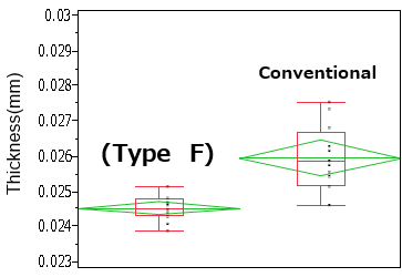
- Good for impedance control as thickness variation is small after press.
- Halogen free material with low CTE values in X, Y directions (α1, α2).
- Good dielectric properties by applying low dielectric glass cloths.
Characteristics
Surface Smoothness of Prepreg (Microscope)
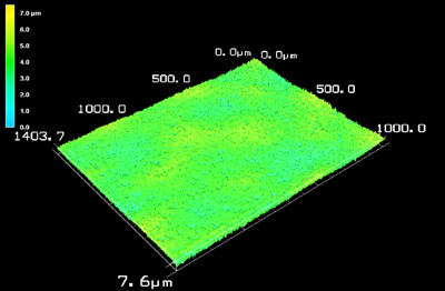
(Type F)
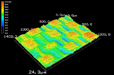
Conventional
Panel Warpage of Prepreg after press (w/o copper, by shadow moire)
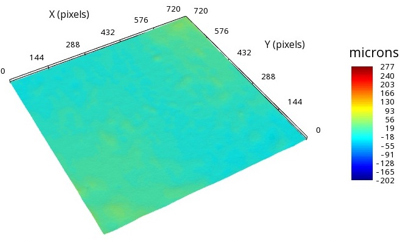
(Type F)
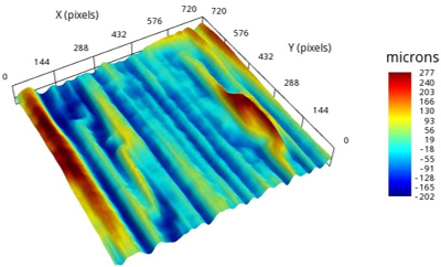
Conventional
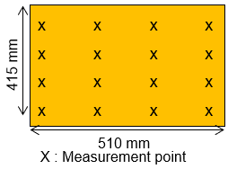
Prepreg thickness after Press
Laminate Condition
-
- GEA-705G1010F78
- Copper foil: 3 µm
- Laminate condition
- Temp.: 230℃100min
- Heating rate: 3.0℃/min
- Pressure: 3MPa
Measurement method
Undulation of prepreg after press (GEA-705G1010F78)
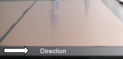
(Type F)
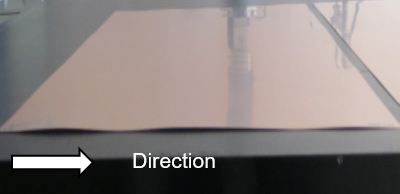
Conventional
Prepreg
| Item | Condition *3 | Unit | Actual Value | Test Method | ||
|---|---|---|---|---|---|---|
| GH-100 (Type DF) |
GH-200 (Type DF) |
(IPC-TM-650) | ||||
| Tg | TMA method | A | ℃ | 240–260 | 220–240 | 2.4.24.5 |
| DMA method | A | 240–260 | 250–270 | – | ||
| CTE *1 (Pull) | X (30–120℃) | A | ppm/℃ | 6–8 | 8–10 | 2.4.24.5 |
| Y (30–120℃) | 6–8 | 8–10 | ||||
| T260 (Without Copper) | A | min. | >60 | >60 | 2.4.24.1 | |
| T288 (Without Copper) | >60 | >60 | ||||
| Dielectric Constant *2 | 10GHz | A | – | 3.5–3.7 | 3.2–3.4 | IEC-62610 |
| Dissipation Factor *2 | 10GHz | A | – | 0.0025–0.0035 | 0.0020–0.0030 | |
*1) Heating Rate: 10℃/min., *2) Measured by cavity resonator method., *3) Refer to “Condition Note”
*Above data are experimental results and not guaranteed.
Standard Specifications
Prepreg
| Part Number | Type | Glass Cloth | Properties | |||
|---|---|---|---|---|---|---|
| Style | Resin Content (%) |
Dielectric Thickness after Lamination *1 (mm) |
||||
| GH-100 | (DF) | 0.025 | 1017F71K | 1017 | 71±2 | 0.027 |
| 1017F73K | 73±2 | 0.029 | ||||
| 1017F75K | 75±2 | 0.031 | ||||
| 1017F77K | 77±2 | 0.034 | ||||
| 1017F79K | 79±2 | 0.038 | ||||
| GH-200 | (DF) | 0.025 | 1017F68K | 1017 | 68±2 | 0.020 |
| 1017F70K | 70±2 | 0.022 | ||||
| 1017F72K | 72±2 | 0.024 | ||||
| 1017F74K | 74±2 | 0.026 | ||||
| 1017F76K | 76±2 | 0.028 | ||||
| 1017F78K | 78±2 | 0.031 | ||||
| 1017F80K | 80±2 | 0.034 | ||||
| 1017F82K | 82±2 | 0.038 | ||||
| 1017F84K | 84±2 | 0.043 | ||||
| Reference (IPC-TM-650) | 2.3.16 | ‐ | ||||
*1) The dielctric thickness after lamination is defined as the thickness of one sheet of prepreg when the resin flow is 0%.
This value changes depending on the press condition or inner layer pattern.
