Base Materials for PWBs
Halogen Free, High Tg, Low Transmission Loss Multilayer Material – MCL-LW-900G/910G
Product Information and Application
Product form
- CCL: MCL-LW-900G/910G
- Prepreg: GWA-900G/910G
Applications
- High-speed computer, server
- High-speed Router
- High Frequency Devices, Antenna
Features
- MCL-LW-910G achieved low dielectric constant (3.3 at 10GHz) and low dissipation factor (0.0028 at 10GHz) using low Dk glass and HVLP copper.
- Enables high-speed transmission/communication at 25Gbps by low transmission loss properties.
- Has excellent heat resistance and connection reliability.
Characteristics
Dielectric characterization results


Measurement Conditions
- Method: Triplate-Line Resonato (r JPCA-TM001)
- Temperature & Humidity: 25℃/60%RH
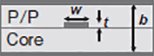
- Laminate Thicknes (s b): 1.6mm (Signal-Ground: 800 µm), Trace thickness(t): 18 µm (RT, HVLP)
- Signal Conductor Line Width(w): 1mm (Zo: ca.50Ω)

Transmission Loss

Measurement Conditions
- Evaluation PWB: Strip-line
- Temperature & Humidity: 25℃/60%RH
- Characteristic impedance: Approx. 50Ω
- Inner layer surface treatment: Black-reduction
- Proofreading method: TRL (Thru-Reflect-Line)
 |
|
|---|
Thin Laminate
(t0.8mm)
| Item | Condition *3 | Unit | Actual Value | Reference (IPC-TM-650) |
|||
|---|---|---|---|---|---|---|---|
| MCL-LW-900G | MCL-LW-910G | ||||||
| Tg | TMA method | A | ℃ | 190–210 | 2.4.24 | ||
| DMA method | A | 220–260 | ‐ | ||||
| CTE *1 | X (30–120℃) | A | ppm/℃ | 12–15 | ‐ | ||
| Y (30–120℃) | 12–15 | ||||||
| Z | (<Tg) | A | 35–45 | 2.4.24 | |||
| (>Tg) | A | 230–280 | |||||
| Solder Heat Resistance (260℃) | A | sec. | >300 | ‐ | |||
| T-260 (Without Copper) | A | min. | >60 | 2.4.24.1 | |||
| T-288 (Without Copper) | >60 | ||||||
| Decomposition Temperature (TGA method 5% Weight Loss) | A | ℃ | 410–450 | 2.3.40 | |||
| Copper Peel Strength | 18 µm RT | A | kN/m | 0.4–0.7 | 2.4.8 | ||
| 18 µm HVLP | 0.4–0.7 | ||||||
| Flexural Modulus (Lengthwise) | A | GPa | 16–21 | 2.4.4 | |||
| Dielectric Constant | 10GHz *2 | A | - | 3.60–3.80 | 3.20–3.40 | IEC-62810 | |
| Dissipation Factor | 10GHz *2 | A | - | 0.0040–0.0050 | 0.0020–0.0030 | ||
| Volume Resistivity | C-96/40/90 | Ω・cm | 1×10¹⁴–1×10¹⁶ | 2.5.7 | |||
| Surface Resistance | C-96/40/90 | Ω | 1×10¹³–1×10¹⁵ | ||||
| Insulation Resistance | A | Ω | 1×10¹⁴–1×10¹⁶ | ‐ | |||
| D-2/100 | 1×10¹²–1×10¹⁴ | ‐ | |||||
*1) Heating Rate: 10℃/min., *2) Measured by Cavity Resonator., *3) Refer to “Condition Note”
*Above data are experimental results and not guaranteed.
Standard Specifications
Copper Clad Laminate
| Part Number | Type | Copper Foil Thickness | Code Name | Laminate Thickness | ||
|---|---|---|---|---|---|---|
| MCL-LW-900G (E glass cloth)MCL-LW-910G (Low Dk glass cloth) |
̶ | 18 µm 35 µm 70 µm (RT)12 µm 18 µm 35 µm (HVLP) |
M0.05 | 0.05mm | ||
| M0.06 | 0.06mm | |||||
| M0.08 | 0.08mm | |||||
| 0.1 | 0.10mm | |||||
| M0.11 | 0.10mm | |||||
| 0.13 | 0.13mm | |||||
| M0.15 | 0.15mm | |||||
| 0.2 | 0.20mm | |||||
| 0.26 | 0.25mm | |||||
Note 1) The thickness means that of dielectric layer.
Prepreg
| Part Number | Type | Glass Cloth | Properties | ||
|---|---|---|---|---|---|
| Style | Resin Content (%) |
Dielectric Thickness after Lamination *1 (mm) |
|||
| GWA-900G | 0.05 | (1037N72) | 1037 | 72±2 | 0.050 |
| 0.06 | (1078N65) | 1078 | 65±2 | 0.078 | |
| 0.08 | (3313N57) | 3313 | 57±2 | 0.106 | |
| 0.1 | (2116N55) | 2116 | 55±2 | 0.125 | |
| GWA-910G | 0.05 | (1037N74) | 1037 | 74±2 | 0.050 |
| 0.06 | (1078N67) | 1078 | 67±2 | 0.078 | |
| 0.08 | (2013N59) | 2013 | 59±2 | 0.106 | |
| 0.1 | (2116N57) | 2116 | 57±2 | 0.125 | |
| Reference (IPC-TM-650) | 2.3.16 | ‐ | |||
*1) The dielectric thickness after lamination is defined as the thickness of one sheet of prepreg when the resin flow is 0%.
This value changes depending on the press condition or inner layer pattern.