Base Materials for PWBs
Thin Prepreg with Superior Surface Smoothness – GEA-705G (Type F), GEA-770G (Type F)
Product Information and Application
Product form
- Prepreg: GEA-705G (Type F), GEA-770G (Type F)
Applications
- Semiconductor packages. (FC-BGA, FC-CSP, PoP, SiP)
- HDI, PWB
- Thinner module, PWB
Features
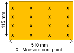
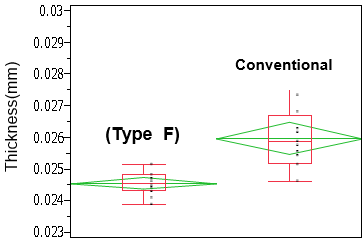
- Superior in impedance control as prepreg thickness variation is small after press.
- Suitable for fine line formation with its smooth surface.
- Can achieve insulation layer thickness 16 µm.
- Suitable for coreless structure by superior variation of dimensional change.
- Undulation of (Type F) prepreg is small after press and warpage can be reduced at assembly.
Characteristics
Surface Smoothness of Prepreg (Microscope)
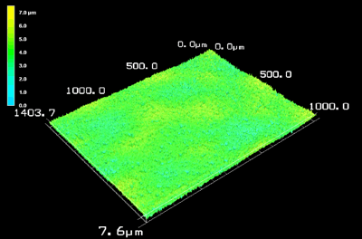
(Type F)
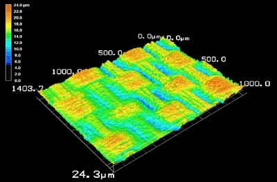
Conventional
Panel Warpage of Prepreg after press (w/o copper, by shadow moire)
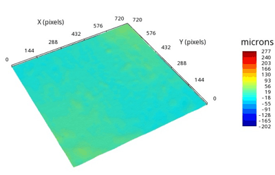
(Type F)
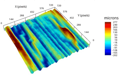
Conventional
Laminate condition (Sample)
- GEA-705G 1010F78
- Copper foil: 3 µm
- Temp.: 230℃100min
- Heating rate: 3.0℃/min
- Pressure: 3MPa
Measurement method
Undulation of prepreg after press (GEA-705G1010F78)
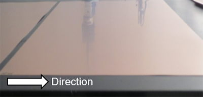
(Type F)
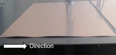
Conventional
Prepreg
| Item | Condition *2 | Unit | Actual Value | Test Method | ||
|---|---|---|---|---|---|---|
| GEA-705G (Type F) | GEA-770G (Type F) | (IPC-TM-650) | ||||
| Tg | TMA method | A | ℃ | 250–270 | 260–280 | 2.4.24.5 |
| DMA method | A | 295–305 | 300–330 | – | ||
| CTE *1 (Pull) | X (30–120℃) | A | ppm/℃ | 8–10 | 6–7 | 2.4.24.5 |
| Y (30–120℃) | 2–5 | 2–4 | ||||
| T260 (Without Copper) | A | min. | >60 | >60 | 2.4.24.1 | |
| T288 (Without Copper) | >60 | >60 | ||||
| Undulation (After Press) | A | mm | 0.0–0.3 | 0.0–0.3 | – | |
*1) Heating Rate: 10℃/min., *2) Refer to “Condition Note”
*Above data are experimental results and not guaranteed.
Standard Specifications
Prepreg
| Part Number | Type | Glass Cloth | Properties | |||
|---|---|---|---|---|---|---|
| Style | Resin Content (%) |
Dielectric Thickness after Lamination *1 (mm) |
||||
| GEA-705G | (F) | 0.020 | 1010F74 | 1010 | 74±2 | 0.021 |
| 1010F76 | 76±2 | 0.023 | ||||
| 1010F78 | 78±2 | 0.025 | ||||
| 1010F80 | 80±2 | 0.027 | ||||
| 1010F84 | 84±2 | 0.035 | ||||
| 0.025 | 1017F73 | 1017 | 73±2 | 0.025 | ||
| 1017F78 | 78±2 | 0.031 | ||||
| 1017F83 | 83±2 | 0.040 | ||||
| GEA-770G | (F) | 0.020 | 1010F67 | 1010 | 67±2 | 0.016 |
| 1010F69 | 69±2 | 0.018 | ||||
| 1010F71 | 71±2 | 0.019 | ||||
| 1010F73 | 73±2 | 0.021 | ||||
| 1010F78 | 78±2 | 0.026 | ||||
| 1010F82 | 82±2 | 0.032 | ||||
| 0.025 | 1017F73 | 1017 | 73±2 | 0.026 | ||
| 1017F78 | 78±2 | 0.033 | ||||
| 1017F83 | 83±2 | 0.043 | ||||
| 0.030 | 1027F73 | 1027 | 73±2 | 0.042 | ||
| 1027F78 | 78±2 | 0.052 | ||||
| Reference (IPC-TM-650) | 2.3.16 | ‐ | ||||
*1) The dielctric thickness after lamination is defined as the thickness of one sheet of prepreg when the resin flow is 0%.
This value changes depending on the press condition or inner layer pattern.
